Android bluetooth介紹(二): android 藍芽程式碼架構及其uart 到rfcomm流程
關鍵詞:藍芽blueZ UART HCI_UART H4 HCI L2CAP RFCOMM
版本:基於android4.2之前版本 bluez
核心:linux/linux3.08
系統:android/android4.1.3.4
作者:xubin341719(歡迎轉載,請註明作者,請尊重版權謝謝)
歡迎指正錯誤,共同學習、共同進步!!
Android bluetooth介紹(一):基本概念及硬體介面
Android bluetooth介紹(二): android 藍芽程式碼架構及其uart 到rfcomm流程
Android bluetooth介紹(三): 藍芽掃描(scan)裝置分析
Android bluetooth介紹(四): a2dp connect流程分析
一、Android Bluetooth Architecture藍芽程式碼架構部分(google 官方藍芽框架)
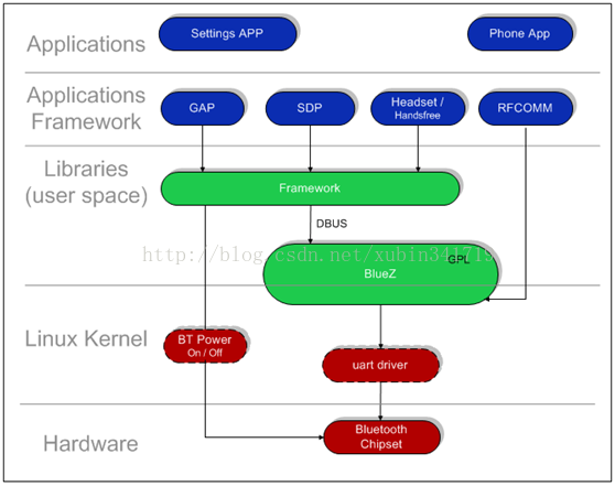
Android的藍芽系統,自下而上包括以下一些內容如上圖所示:
1、串列埠驅動
Linux的核心的藍芽驅動程、Linux的核心的藍芽協議的層
2、BlueZ的介面卡
BlueZ的(藍芽在使用者空間的函式庫)
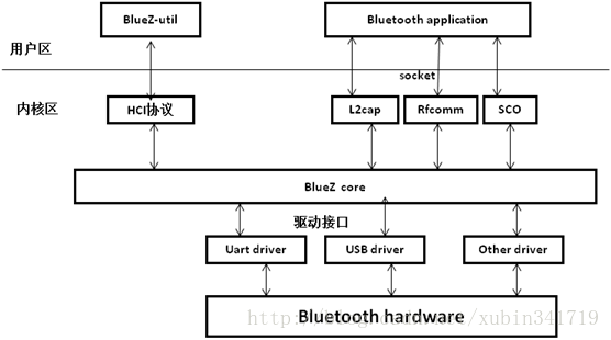
bluez程式碼結構
Bluetooth協議棧BlueZ分為兩部分:核心程式碼和使用者態程式及工具集。
(1)、核心程式碼:由BlueZ核心協議和驅動程式組成
Bluetooth協議實現在核心原始碼 kernel/net/bluetooth中。包括hci,l2cap,hid,rfcomm,sco,SDP,BNEP等協議的實現。
(2)、驅動程式:kernel/driver/bluetooth中,包含Linuxkernel對各種介面的
Bluetooth device的驅動,如:USB介面,串列埠等。
(3)、使用者態程式及工具集:
包括應用程式介面和BlueZ工具集。BlueZ提供函式庫以及應用程式介面,便於程式設計師開發bluetooth應用程式。BlueZ utils是主要工具集,實現對bluetooth裝置的初始化和控制。
3、藍芽相關的應用程式介面
Android.buletooth包中的各個Class(藍芽在框架層的內容-----java)
|
類名 |
作用 |
|
BluetoothAdapter |
本地藍芽裝置的適配類,所有的藍芽操作都要通過該類完成 |
|
BluetoothClass |
用於描述遠端裝置的型別,特點等資訊 |
|
BluetoothDevice |
藍芽裝置類,代表了藍芽通訊過程中的遠端裝置 |
|
BluetoothServerSocket |
藍芽裝置服務端,類似ServerSocket |
|
BluetoothSocket |
藍芽裝置客戶端,類似Socket |
|
BluetoothClass.Device |
藍芽關於裝置資訊 |
|
BluetoothClass.Device.Major |
藍芽裝置管理 |
|
BluetoothClass.Service |
藍芽相關服務 |
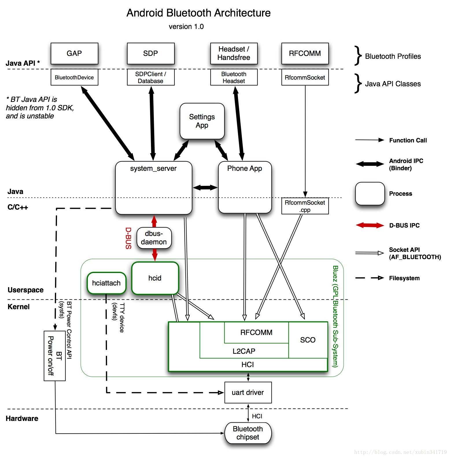
同樣下圖也是一張比較經典的藍芽程式碼架構圖(google官方提供)
二、藍芽通過Hciattach啟動串列埠流程:
1、hciattach總體流程
2、展訊hciattach程式碼實現流程:

三、具體程式碼分析
1、initrc中定義
idh.code\device\sprd\sp8830ec_nwcn\init.sc8830.rc
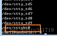
- service hciattach /system/bin/hciattach -n /dev/sttybt0 sprd_shark
- socket bluetooth stream 660 bluetooth bluetooth
- user bluetooth
- group wifi bluetooth net_bt_admin net_bt inet net_raw net_admin system
- disabled
- oneshot
adb 下/dev/ttybt0(不同平臺有所不同)
PS 程式中:hicattch
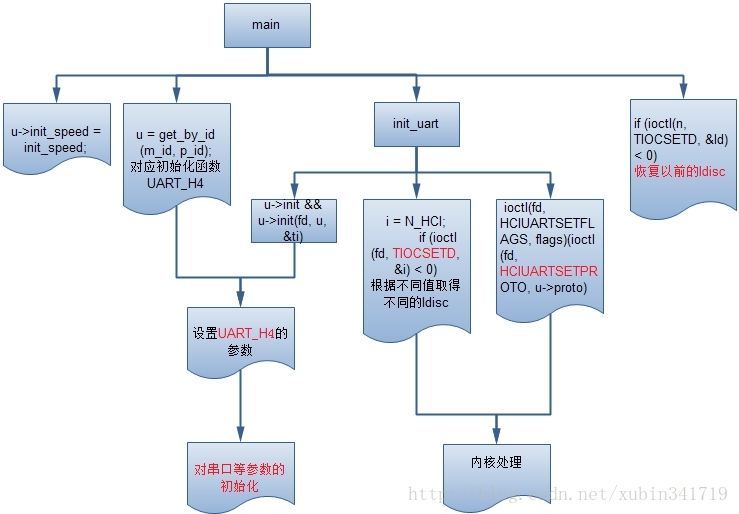
2、/system/bin/hciattach 執行的Main函式
idh.code\external\bluetooth\bluez\tools\hciattach.c
service hciattach /system/bin/hciattach -n /dev/sttybt0 sprd_shark
傳進兩個引數,/dev/sttybt0 和 sprd_shark
- nt main(int argc, char *argv[])
- {
- ………………
- for (n = 0; optind < argc; n++, optind++) {
- char *opt;
- opt = argv[optind];
- switch(n) {
- case 0://(1)、解析驅動的位置;
- dev[0] = 0;
- if (!strchr(opt, '/'))
- strcpy(dev, "/dev/");
- strcat(dev, opt);
- break;
- case 1://(2)、解析串列埠的配置相關引數;
- if (strchr(argv[optind], ',')) {
- int m_id, p_id;
- sscanf(argv[optind], "%x,%x", &m_id, &p_id);
- u = get_by_id(m_id, p_id);
- } else {
- u = get_by_type(opt);
- }
- if (!u) {
- fprintf(stderr, "Unknown device type or id\n");
- exit(1);
- }
- break;
- case 2://(3)、通過對前面引數的解析,把uart[i]中的數值初始化;
- u->speed = atoi(argv[optind]);
- break;
- case 3:
- if (!strcmp("flow", argv[optind]))
- u->flags |= FLOW_CTL;
- else
- u->flags &= ~FLOW_CTL;
- break;
- case 4:
- if (!strcmp("sleep", argv[optind]))
- u->pm = ENABLE_PM;
- else
- u->pm = DISABLE_PM;
- break;
- case 5:
- u->bdaddr = argv[optind];
- break;
- }
- }
- ………………
- if (init_speed)//初始化串列埠速率;
- u->init_speed = init_speed;
- ………………
- n = init_uart(dev, u, send_break, raw);//(4)、初始化串列埠;
- ………………
- return 0;
- }
(1)、解析驅動的位置;
- if (!strchr(opt, '/'))
- strcpy(dev, "/dev/");
- service hciattach /system/bin/hciattach -n /dev/sttybt0 sprd_shark
- dev = /dev/ttyb0
(2)、解析串列埠的配置相關引數;獲取引數對應的結構體;
- u = get_by_id(m_id, p_id);
- static struct uart_t * get_by_id(int m_id, int p_id)
- {
- int i;
- for (i = 0; uart[i].type; i++) {
- if (uart[i].m_id == m_id && uart[i].p_id == p_id)
- return &uart[i];
- }
- return NULL;
- }
這個函式比較簡單,通過迴圈對比,如傳進了的引數sprd_shark和uart結構體中的對比,找到對應的陣列。如果是其他藍芽晶片,如博通、RDA、BEKN等著到其相對應的初始化配置函式。
- struct uart_t uart[] = {
- { "any", 0x0000, 0x0000, HCI_UART_H4, 115200, 115200,
- FLOW_CTL, DISABLE_PM, NULL, NULL },
- { "sprd_shark", 0x0000, 0x0000, HCI_UART_H4, 115200, 115200,
- FLOW_CTL, DISABLE_PM, NULL, init_sprd_config },
- { "ericsson", 0x0000, 0x0000, HCI_UART_H4, 57600, 115200,
- FLOW_CTL, DISABLE_PM, NULL, ericsson },
- ………………
- { "bk3211", 0x0000, 0x0000, HCI_UART_BCSP, 115200, 921600, 0, DISABLE_PM, NULL, beken_init, NULL},
- { NULL, 0 }
- };
注意:init_sprd_config這個函式在uart_init中用到,這個函式其實對我們具體晶片的初始化配置。
註釋:HCI_UART_H4和HCI_UART_BCSP的區別如下圖。

(3)、通過對前面引數的解析,把uart[i]中的數值初始化;
- u->speed = atoi(argv[optind]);
- break;
(4)、初始化串列埠;
- n = init_uart(dev, u, send_break, raw);
- idh.code\external\bluetooth\bluez\tools\hciattach.c
- /* Initialize UART driver */
- int init_uart(char *dev, struct uart_t *u, int send_break)
- {
- struct termios ti;
- int fd, i;
- fd = open(dev, O_RDWR | O_NOCTTY);//開啟串列埠裝置,其中標誌
- //O_RDWR,可以對此裝置進行讀寫操作;
- //O_NOCTTY:告訴Unix這個程式不想成為“控制終端”控制的程式,不說明這個標誌的話,任何輸入都會影響你的程式。
- //O_NDELAY:告訴Unix這個程式不關心DCD訊號線狀態,即其他埠是否執行,不說明這個標誌的話,該程式就會在DCD訊號線為低電平時停止。
- //但是不要以控制 tty 的模式,因為我們並不希望在傳送 Ctrl-C
- 後結束此程式
- if (fd < 0) {
- perror(“Can’t open serial port”);
- return -1;
- }
- //drop fd’s data;
- tcflush(fd, TCIOFLUSH);//清空資料線
- if (tcgetattr(fd, &ti) < 0) {
- perror(“Can’t get port settings”);
- return -1;
- }
- cfmakeraw(&ti);
- cfmakeraw sets the terminal attributes as follows://此函式設定串列埠終端的以下這些屬性,
- termios_p->c_iflag &= ~(IGNBRK|BRKINT|PARMRK|ISTRIP
- |INLCR|IGNCR|ICRNL|IXON);
- termios_p->c_oflag &= ~OPOST;
- termios_p->c_lflag &= ~(ECHO|ECHONL|ICANON|ISIG|IEXTEN);
- termios_p->c_cflag &= ~(CSIZE|PARENB) ;
- termios_p->c_cflag |=CS8;
- ti.c_cflag |= CLOCAL;//本地連線,無調變解調器控制
- if (u->flags & FLOW_CTL)
- ti.c_cflag |= CRTSCTS;//輸出硬體流控
- else
- ti.c_cflag &= ~CRTSCTS;
- if (tcsetattr(fd, TCSANOW, &ti) < 0) {//啟動新的串列埠設定
- perror(“Can’t set port settings”);
- return -1;
- }
- /* Set initial baudrate */
- if (set_speed(fd, &ti, u->init_speed) < 0) {//設定串列埠的傳輸速率bps, 也可以使
- //用 cfsetispeed 和 cfsetospeed 來設定
- perror(“Can’t set initial baud rate”);
- return -1;
- }
- tcflush(fd, TCIOFLUSH);//清空資料線
- if (send_break)
- tcsendbreak(fd, 0);
- //int tcsendbreak ( int fd, int duration );Sends a break for
- //the given time.在串列埠線上傳送0值,至少維持0.25秒。
- //If duration is 0, it transmits zero-valued bits for at least 0.25 seconds, and
- //not more than 0.5seconds.
- //where place register u’s init function;
- if (u->init && u->init(fd, u, &ti) < 0)
- //所有bluez支援的藍芽串列埠裝置型別構成了一個uart結構陣列,通過
- //查詢對應的uart型別,這個uart的init成員顯示了它的init呼叫方法;
- struct uart_t uart[] = {
- { "any", 0x0000, 0x0000, HCI_UART_H4, 115200, 115200,FLOW_CTL, DISABLE_PM, NULL, NULL },
- { "sprd_shark", 0x0000, 0x0000, HCI_UART_H4, 115200, 115200,FLOW_CTL, DISABLE_PM, NULL, init_sprd_config },
- { "ericsson", 0x0000, 0x0000, HCI_UART_H4, 57600, 115200,FLOW_CTL, DISABLE_PM, NULL, ericsson },
- ………………
- { "bk3211", 0x0000, 0x0000, HCI_UART_BCSP, 115200, 921600, 0, DISABLE_PM, NULL, beken_init, NULL},
- { NULL, 0的init函式名為bcsp,定義在本檔案中**;
- return -1;
- tcflush(fd, TCIOFLUSH);//清空資料線
- /* Set actual baudrate */
- if (set_speed(fd, &ti, u->speed) < 0) {
- perror(“Can’t set baud rate”);
- return -1;
- }
- /* Set TTY to N_HCI line discipline */
- i = N_HCI;
- if (ioctl(fd, TIOCSETD, &i) < 0) {//
- TIOCSETD int *ldisc//改變到 i 行規,即hci行規
- Change to the new line discipline pointed to by ldisc. The available line disciplines are listed in
- /* ioctl (fd, TIOCSERGETLSR, &result) where result may be as below */
- /* line disciplines */
- #define N_TTY 0
- ……
- #define N_HCI 15 /* Bluetooth HCI UART */
- perror(“Can’t set line discipline”);
- return -1;
- }
- if (ioctl(fd, HCIUARTSETPROTO, u->proto) < 0) {
- //設定hci裝置的proto操作函式集為hci_uart操作集;
- perror(“Can’t set device”);
- return -1;
- }
- return fd;
- }
這裡一個重要的部分是:u->init指向init_sprd_config
4、uart具體到晶片的初始化init_sprd_config(這部分根據不同的晶片,對應進入其相應初始化部分)
idh.code\external\bluetooth\bluez\tools\hciattach_sprd.c
- int sprd_config_init(int fd, char *bdaddr, struct termios *ti)
- {
- int i,psk_fd,fd_btaddr,ret = 0,r,size=0,read_btmac=0;
- unsigned char resp[30];
- BT_PSKEY_CONFIG_T bt_para_tmp;
- char bt_mac[30] = {0};
- char bt_mac_tmp[20] = {0};
- uint8 bt_mac_bin[32] = {0};
- fprintf(stderr,"init_sprd_config in \n");
- //(1)、這部分檢查bt_mac,如果存在,從檔案中讀取,如果不存在,隨機生成,並寫入相應檔案;
- if(access(BT_MAC_FILE, F_OK) == 0) {//這部分檢查bt_mac
- LOGD("%s: %s exists",__FUNCTION__, BT_MAC_FILE);
- fd_btaddr = open(BT_MAC_FILE, O_RDWR);// #define BT_MAC_FILE "/productinfo/btmac.txt"
- if(fd_btaddr>=0) {
- size = read(fd_btaddr, bt_mac, sizeof(bt_mac));//讀取BT_MAC_FILE中的地址;
- LOGD("%s: read %s %s, size=%d",__FUNCTION__, BT_MAC_FILE, bt_mac, size);
- if(size == BT_RAND_MAC_LENGTH){
- LOGD("bt mac already exists, no need to random it");
- fprintf(stderr, "read btmac ok \n");
- read_btmac=1;
- }
- …………
- }else{//如果不存在,就隨機生成一個bt_mac地址,寫入/productinfo/btmac.txt
- fprintf(stderr, "btmac.txt not exsit!\n");
- read_btmac=0;
- mac_rand(bt_mac);
- LOGD("bt random mac=%s",bt_mac);
- printf("bt_mac=%s\n",bt_mac);
- write_btmac2file(bt_mac);
- fd_btaddr = open(BT_MAC_FILE, O_RDWR);
- if(fd_btaddr>=0) {
- size = read(fd_btaddr, bt_mac, sizeof(bt_mac));
- LOGD("%s: read %s %s, size=%d",__FUNCTION__, BT_MAC_FILE, bt_mac, size);
- if(size == BT_RAND_MAC_LENGTH){
- LOGD("bt mac already exists, no need to random it");
- fprintf(stderr, "read btmac ok \n");
- read_btmac=1;
- }
- close(fd_btaddr);
- …………
- }
- /* Reset the BT Chip */
- memset(resp, 0, sizeof(resp));
- memset(&bt_para_tmp, 0, sizeof(BT_PSKEY_CONFIG_T) );
- ret = getPskeyFromFile( (void *)(&bt_para_tmp) );//ret = get_pskey_from_file(&bt_para_tmp);//(2)、PSKey引數、射頻引數的設定;
- if(ret != 0){//引數失敗處理
- fprintf(stderr, "get_pskey_from_file faill \n");
- /* Send command from hciattach*/
- if(read_btmac == 1){
- memcpy(bt_para_setting.device_addr, bt_mac_bin, sizeof(bt_para_setting.device_addr));// (3)、讀取失敗,把bt_para_setting中defaut引數寫入;
- }
- if (write(fd, (char *)&bt_para_setting, sizeof(BT_PSKEY_CONFIG_T)) != sizeof(BT_PSKEY_CONFIG_T)) {
- fprintf(stderr, "Failed to write reset command\n");
- return -1;
- }
- }else{//getpskey成功處理
- /* Send command from pskey_bt.txt*/
- if(read_btmac == 1){
- memcpy(bt_para_tmp.device_addr, bt_mac_bin, sizeof(bt_para_tmp.device_addr));
- }
- …………
- return 0;
- }
(1)、這部分檢查bt_mac,如果存在,從檔案中讀取,如果不存在,隨機生成,並寫入相應檔案/productinfo/btmac.txt;
(2)、PSKey引數、射頻引數的設定;
get_pskey_from_file(&bt_para_tmp);這個函式後面分析;
(3)、讀取失敗,把bt_para_setting中defaut引數寫入;頻率、主從裝置設定等……
- // pskey file structure default value
- BT_PSKEY_CONFIG_T bt_para_setting={
- 5,
- 0,
- 0,
- 0,
- 0,
- 0x18cba80,
- 0x001f00,
- 0x1e,
- {0x7a00,0x7600,0x7200,0x5200,0x2300,0x0300},
- …………
- };
5、get_pskey_from_file 解析相關射頻引數
idh.code\external\bluetooth\bluez\tools\pskey_get.c
- int getPskeyFromFile(void *pData)
- {
- …………
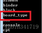
- char *BOARD_TYPE_PATH = "/dev/board_type";//(1)、判斷PCB的版本;
- int fd_board_type;
- char board_type_str[MAX_BOARD_TYPE_LEN] = {0};
- int board_type;
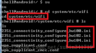
- char *CFG_2351_PATH_2 = "/productinfo/2351_connectivity_configure.ini";//(2)、最終生成ini檔案儲存的位置;
- char *CFG_2351_PATH[MAX_BOARD_TYPE];
- (3)、針對不同PCB版本,不同的ini配置檔案;
- CFG_2351_PATH[0] = "/system/etc/wifi/2351_connectivity_configure_hw100.ini";
- CFG_2351_PATH[1] = "/system/etc/wifi/2351_connectivity_configure_hw102.ini";
- CFG_2351_PATH[2] = "/system/etc/wifi/2351_connectivity_configure_hw104.ini";
(4)、下面函式就不做具體分析,大致意識是,根據/dev/board_type中,讀取的PCB型別,設定不同的ini檔案。
- ………………
- ret = chmod(CFG_2351_PATH_2, 0644);
- ALOGE("chmod 0664 %s ret:%d\n", CFG_2351_PATH_2, ret);
- if(pBuf == pBuf2)
- free(pBuf1);
- ………………
- }
(1)、判斷PCB的版本;
char *BOARD_TYPE_PATH = "/dev/board_type";
(2)、最終生成ini檔案儲存的位置,就是系統執行時讀取ini檔案的地方;
char *CFG_2351_PATH_2 ="/productinfo/2351_connectivity_configure.ini";
(3)、針對不同PCB版本,不同的ini配置檔案;
- CFG_2351_PATH[0] = "/system/etc/wifi/2351_connectivity_configure_hw100.ini";
- CFG_2351_PATH[1] = "/system/etc/wifi/2351_connectivity_configure_hw102.ini";
- CFG_2351_PATH[2] = "/system/etc/wifi/2351_connectivity_configure_hw104.ini";
(4)、下面函式就不做具體分析,大致意識是,根據/dev/board_type中,讀取的PCB型別,設定不同的ini檔案。 覆蓋到(2)中的檔案。
四、HCI_UART_H4和H4層的加入
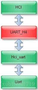
uart->hci_uart->Uart-H4->hci:從uart開始分析,介紹整個驅動層資料流(涉及tty_uart中斷, 線路層ldisc_bcsp、tasklet、work queue、skb_buffer的等)
這是資料的流動過程,最底層的也就是和硬體打交道的是uart層了,它的存在和起作用是通過串列埠驅動來保證的,這個請參閱附錄,但是其它的層我們都不知道什麼時候work的,下面來看。
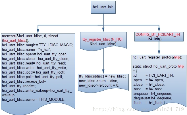
1、idh.code\kernel\drivers\bluetooth\hci_ldisc.c
- static int __init hci_uart_init(void)
- {
- static struct tty_ldisc_ops hci_uart_ldisc;
- int err;
- /* Register the tty discipline */
- memset(&hci_uart_ldisc, 0, sizeof (hci_uart_ldisc));
- hci_uart_ldisc.magic = TTY_LDISC_MAGIC;
- hci_uart_ldisc.name = "n_hci";
- hci_uart_ldisc.open = hci_uart_tty_open;
- hci_uart_ldisc.close = hci_uart_tty_close;
- hci_uart_ldisc.read = hci_uart_tty_read;
- hci_uart_ldisc.write = hci_uart_tty_write;
- hci_uart_ldisc.ioctl = hci_uart_tty_ioctl;
- hci_uart_ldisc.poll = hci_uart_tty_poll;
- hci_uart_ldisc.receive_buf = hci_uart_tty_receive;
- hci_uart_ldisc.write_wakeup = hci_uart_tty_wakeup;
- hci_uart_ldisc.owner = THIS_MODULE;
- if ((err = tty_register_ldisc(N_HCI, &hci_uart_ldisc))) {//(1)、這部分完成ldisc的註冊;
- BT_ERR("HCI line discipline registration failed. (%d)", err);
- return err;
- }
- #ifdef CONFIG_BT_HCIUART_H4
- h4_init();//(2)、我們藍芽晶片用的是H4,這部分完成H4的註冊;
- #endif
- #ifdef CONFIG_BT_HCIUART_BCSP
- bcsp_init();
- #endif
- ………………
- return 0;
- }
(1)、這部分完成ldisc的註冊;
tty_register_ldisc(N_HCI,&hci_uart_ldisc)
註冊了一個ldisc,這是通過把新的ldisc放在一個ldisc的陣列裡面實現的,tty_ldiscs是一個全域性的ldisc陣列裡面會根據序號對應一個ldisc,這個序號就是上層通過ioctl來指定的,比如我們在前面已經看到的:
i = N_HCI;
ioctl(fd, TIOCSETD, &i) < 0
可以看到這裡指定的N_HCI剛好就是這裡註冊的這個號碼15;
(2)、藍芽晶片用的是H4,這部分完成H4的註冊;
h4_init();
hci_uart_proto結構體的初始化:
idh.code\kernel\drivers\bluetooth\hci_h4.c
- static struct hci_uart_proto h4p = {
- .id = HCI_UART_H4,
- .open = h4_open,
- .close = h4_close,
- .recv = h4_recv,
- .enqueue = h4_enqueue,
- .dequeue = h4_dequeue,
- .flush = h4_flush,
- };
H4的註冊:
idh.code\kernel\drivers\bluetooth\hci_h4.c
- int __init h4_init(void)
- {
- int err = hci_uart_register_proto(&h4p);
- if (!err)
- BT_INFO("HCI H4 protocol initialized");
- else
- BT_ERR("HCI H4 protocol registration failed");
- return err;
- }
這是通過hci_uart_register_proto(&bcsp)來完成的,這個函式非常簡單,本質如下:
hup[p->id]= p;其中static struct hci_uart_proto*hup[HCI_UART_MAX_PROTO];也就是說把對應於協議p的id和協議p連線起來,這樣設計的好處是hci uart層本身可以支援不同的協議,包括h4、bcsp等,通過這個陣列連線這些協議,等以後有資料的時候呼叫對應的協議來處理,這裡比較關鍵的是h4裡面的這些函式。
五、HCI層的加入
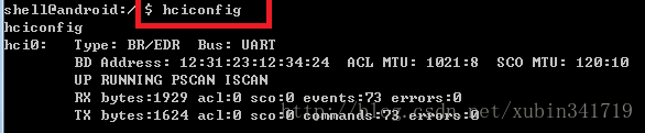
hci的加入是通過hci_register_dev函式來做的,這時候使用者通過hciconfig就可以看到有一個介面了,通過這個介面使用者可以訪問底層的資訊了,hci0已經生成;至於它在何時被加入的,我們再看看hciattach在核心裡面的處理過程;

1、TIOCSEATD的處理流程

Ioctl的作用是設定一個新的ldisc;
2、HCIUARTSETPROTO的處理流程:
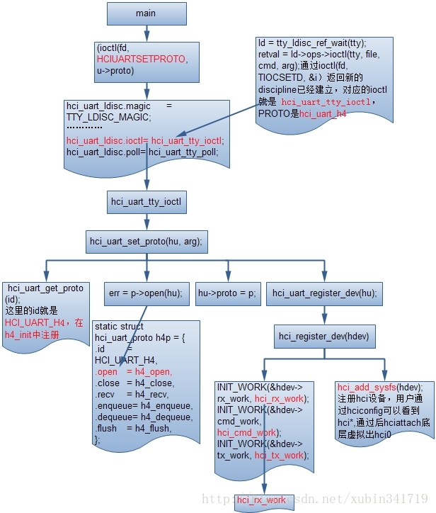
這部分比較重要,註冊生成hci0, 初始化3個工作佇列,hci_rx_work、hci_tx_work、hci_cmd_work;完成hci部分資料、命令的接收、傳送。
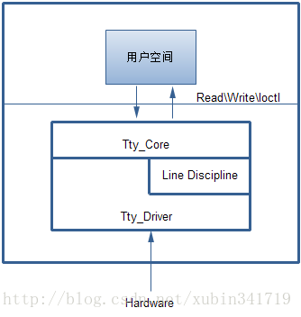
六、資料在驅動的傳遞流程
1、uart資料接收
這部分流程比較簡單,其實就是註冊一個tty驅動程式和相對應的函式,註冊相應的open\close\ioctl等方法,通過應用open /dev/ttyS*操作,註冊中斷接收函式,接收處理藍芽模組觸發中斷的資料。
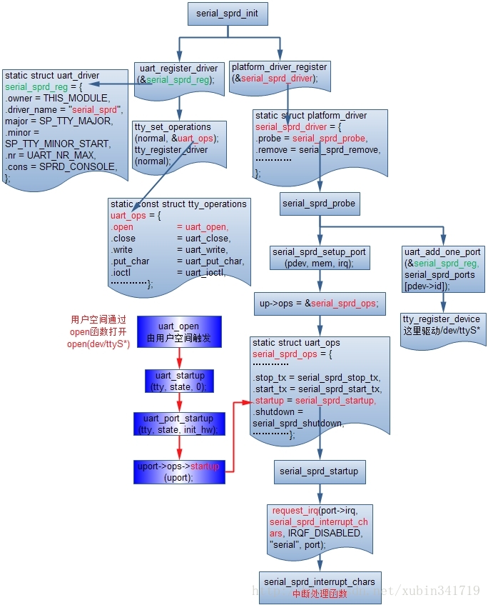
在這個中斷函式裡面會接受到來自於藍芽模組的資料;在中斷函式裡面會先讀取串列埠的狀態暫存器判斷是否是data準備好,如果準備好就呼叫serial_sprd_rx_chars函式來接收資料,下面看看這個函式是如何處理的:
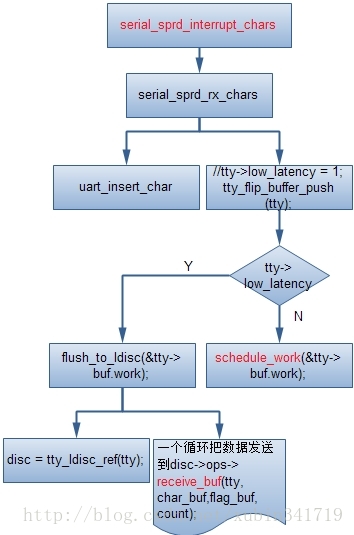
那就是把資料一個個的加入到uart層的緩衝區,直到底層不處於dataready狀態,或者讀了maxcount個數,當讀完後就呼叫tty層的介面把資料傳遞給tty層,tty層則把資料交給了ldisc,於是控制權也就交給了hci_uart層;
七、Hci_uart的資料接收
它基本上就是要個二傳手,通過:
- spin_lock(&hu->rx_lock);
- hu->proto->recv(hu,(void *) data, count);
- hu->hdev->stat.byte_rx+= count;
- spin_unlock(&hu->rx_lock);
八、H4層處理
這層主要是通過函式h4_recv來處理的,根據協議處理包頭、CRC等,然後呼叫更上層的hci_recv_frame來處理已經剝去h4包頭的資料;
如圖:
九、HCI以上的處理


這裡的hci_rx_work前面已經看到它了,它是一個工作佇列用來處理hci層的資料接收的;先看是否有程式開啟hci的socket用來監聽資料,如果有的話,就把資料的一個copy傳送給它,然後根據包的型別呼叫不同的處理函式,分別對應於event、acl、sco處理;
hci_event_packet是對於事件的處理,裡面包含有包括掃描,訊號,授權,pin碼,總之基本上上層所能收到的事件,基本都是在這裡處理的,它的很多資訊都是先存起來,等待上層的查詢然後才告訴上層;
hci_acldata_packet是一個經常的情況,也就是說上層通常都是使用的是l2cap層的介面,而l2cap就是基於這個的,如下圖所示:
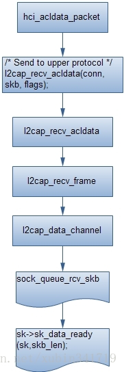
到這裡如果有基於BTPROTO_L2CAP的socket,那麼這個socket就可以收到資料了;再看看BTPROTO_RFCOMM的流程:

十、 資料流程的總結
簡單總結一下,資料的流程,
|基本上是:
1, uart口取得藍芽模組的資料;
2, uart口通過ldisc傳給hci_uart;
3, hci_uart傳給在其上的h4;
4, h4傳給hci層;
5, hci層傳給l2cap層
6, l2cap層再傳給rfcomm;
相關文章
- Android 4.2藍芽介紹Android藍芽
- Android藍芽那點事——深入瞭解Android藍芽Bluetooth《進階篇》Android藍芽
- BLE藍芽那些事—深入瞭解Android藍芽Bluetooth基礎篇藍芽Android
- 深入瞭解Android藍芽Bluetooth——《基礎篇》Android藍芽
- Android 開啟藍芽流程Android藍芽
- Android藍芽開發流程實踐Android藍芽
- android藍芽BLE(二) —— 通訊Android藍芽
- android 4.0 藍芽分析之二Android藍芽
- 五十一、【Bluetooth藍芽模組】藍芽模組
- android bluetooth——藍芽的開啟、搜尋、配對與連線Android藍芽
- Android的Camera架構介紹Android架構
- Android Studio 藍芽 示例程式碼(轉)Android藍芽
- Android平臺架構的介紹和原始碼分析Android架構原始碼
- 藍芽(Bluetooth)音訊協議藍芽音訊協議
- Android藍芽使用詳解(普通藍芽)Android藍芽
- android藍芽hal層程式碼跟蹤記錄Android藍芽
- 藍芽Bluetooth技術小知識藍芽
- Android藍芽協議-藍芽掃描 startDiscoveryAndroid藍芽協議
- Nginx 架構——【核心流程+模組介紹】Nginx架構
- nginx介紹(二) 架構篇Nginx架構
- Android開發--藍芽操作Android藍芽
- Android-藍芽聊天demoAndroid藍芽
- Android Ble藍芽入門Android藍芽
- iOS藍芽開發 Bluetooth藍芽CoreBluetooth 藍芽中心裝置的實現 藍芽外設的實現 有DemoiOS藍芽
- Android藍芽那點事——深入瞭解藍芽BlE藍芽 《總結篇》Android藍芽
- Android Architecture Blueprints(架構藍圖)Android架構
- android藍芽BLE(三) —— 廣播Android藍芽
- android藍芽BLE(一) —— 掃描Android藍芽
- Android 傳統藍芽開發Android藍芽
- Android 藍芽音響開發Android藍芽
- android 4.0 藍芽分析之一Android藍芽
- Android藍芽串列埠通訊Android藍芽串列埠
- 遠端攻擊Android藍芽Android藍芽
- Android 程式目錄介紹Android
- Android 圖形架構簡介Android架構
- 程式碼構建軟體架構圖的工具介紹架構
- 【Android系統】Android系統架構簡介Android架構
- 藍芽工作流程藍芽