【龍印】龍芯1c上雙路16位AD晶片TM7705的linux驅動
本文為在用龍芯1c做3D印表機過程中的筆記。龍芯1c做的3d印表機簡稱“龍印”,git地址“https://gitee.com/caogos/marlin_ls1c”
TM7705和熱敏電阻一起實現3d印表機的溫度測量。本文重點放在tm7705的linux驅動上,關於溫度測量後面另外寫一篇詳細介紹。
硬體電路
測試用的硬體為“安富萊”推出的TM7705模組。這裡著重強調一下TM7705是深圳天微電子的AD晶片,很多淘寶商家把名字都寫錯了。
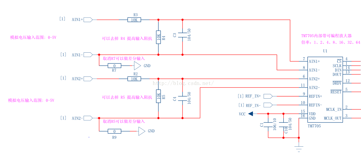
為了使原理圖更加清晰,把整個原理圖分成了幾塊分別截圖了。下面談點個人對本模組的理解,僅供參考。
1,本模組的模擬輸入端AIN1+,AIN1-和AIN2+,AIN2-分別通過兩個10k電阻並聯分壓。這樣的目的是為了把輸入電壓範圍從0-2.5v擴大到0-5v,即滿量程電壓為5v。
因為使用的是2.5v的基準電源,所以實際上AIN引腳的輸入範圍為0-2.5v,通過兩個10k電阻分壓,而AIN1+和AIN2+則接到兩個10k電阻中間,這樣就實現了把測量範圍從0-2.5v擴大到0-5v。凡事有兩面性,正是由於引入了兩個10k電阻,同時也引入了誤差。
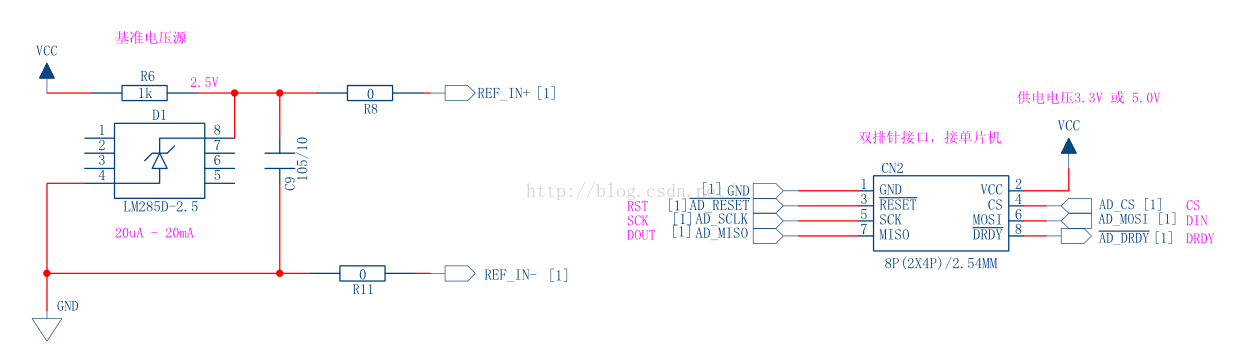
2,這個模組使用的參考電源是2.5v的,tm7705允許參考電源電壓為0到vdd之間的任意值。
對於使用在3d印表機上來說,最後改為3.3v或者5v的參考電源(如果有的話)。marlin中有個指令碼createTemperatureLookup.py可以生成一個AD值與溫度對應的表格,用於程式中快速計算溫度值。
假如待測試的電壓很小,比如是毫伏級的,那麼可以選擇電源低一些的基準電源,這樣有利於提高精度,同時如果需要,可以把增益設定大一點,tm7705最大可以支援128的增益。
3,tm7705是支援3.3v和5v供電的,具體選擇哪個根據spi sclk的電平決定。如果SPI的SCLK線上的高電平為3.3v,那麼推薦使用3.3v的電源給tm7705供電。比如龍芯1c的spi的SCLK是3.3v的,如果tm7705的vdd接5v,那麼出現介面迷失的概率大大增加。
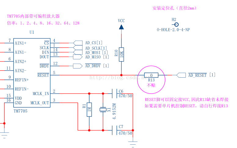
4,復位(reset)引腳。我在這裡犯了低階錯誤,拿到電路圖後,發現圖上說已經上拉到vcc了,並且R13沒貼。後面在接線時沒接復位腳,懸空的;移植tm7705驅動時,沒有操作復位腳。後來發現tm7705採集始終不是很穩定,每次上電後可以成功採集幾次,過後就超時,或者一直採集到的值為0xfff,並且把龍芯1c熱復位還不一定能解決。用示波器檢查了,沒發現問題,程式碼也檢查了,沒發現問題。經過兩週的煎熬後,突然想起來把R13焊上,用軟體復位tm7705試試。結果發現一切OK,並且後續如果出錯,通過復位tm7705也都能解決,今天我從上午不斷電連續測到現在都沒問題。即使超時了,程式碼中也通過復位tm7705很快就解決了。
所以這裡強烈建議:把tm7705復位腳接龍芯1c的一個gpio,每次上電後初始化時必須手動復位tm7705,如果出現超時或其它錯誤時,也可以通過復位tm7705來解決。
tm7705模組使用龍芯1c的SPI0_CS1
RESET -------- I2S_LRCK/GPIO89
VDD -------- 3.3V
原始碼
在檔案arch\mips\loongson\ls1x\ls1c\platform.c中,
找到“static struct spi_board_info ls1x_spi0_devices[]”,在裡面新增
#ifdef CONFIG_SPI_TM7705
    {
        .modalias       = "TM7705",
        .bus_num        = 0,
        .chip_select    = SPI0_CS1,
        // 當前cpu頻率=252.00Mhz BUS=126.00Mhz
        // SPI最大的分頻係數為4096
        // 所以spi最小頻率=126Mhz/4096=30.7khz
        // 這裡只是設定最大頻率,實際頻率為最接近並且小於最大頻率的BUS分頻後的值
        // 經過測試,最大頻率設為為1mhz也能正常採集
        .max_speed_hz   = 500*1000,
//        .platform_data  =
        .mode           = SPI_MODE_3,
    },
#endif
tm7705.c
/*
 *
 * 雙路16位spi介面AD晶片--TM7705的驅動
 */


#include <linux/module.h>
#include <linux/kernel.h>
#include <linux/init.h>
#include <linux/platform_device.h>
#include <linux/interrupt.h>
#include <linux/err.h>
#include <linux/miscdevice.h>
#include <linux/gpio.h>
#include <linux/delay.h>
#include <linux/signal.h>
#include <linux/sched.h>
#include <linux/fs.h>
#include <linux/time.h>
#include <linux/errno.h>
#include <linux/clk.h>
#include <linux/mutex.h>
#include <linux/kfifo.h>
#include <linux/spi/spi.h>
#include <linux/slab.h>
#include <linux/device.h>
#include <linux/sysfs.h>
#include <linux/hwmon.h>
#include <linux/hwmon-sysfs.h>


// 通訊暫存器bit定義
enum
{
	// 暫存器選擇  RS2 RS1 RS0
	TM7705_REG_COMM	        = (0 << 4), // 通訊暫存器
	TM7705_REG_SETUP	    = (1 << 4), // 設定暫存器
	TM7705_REG_CLOCK	    = (2 << 4), // 時鐘暫存器
	TM7705_REG_DATA	        = (3 << 4), // 資料暫存器
	TM7705_REG_TEST         = (4 << 4), // 測試暫存器
	TM7705_REG_OFFSET       = (6 << 4), // 偏移暫存器
	TM7705_REG_GAIN         = (7 << 4), // 增益暫存器

    // 讀寫操作
	TM7705_WRITE 		    = (0 << 3), // 寫操作
	TM7705_READ 		    = (1 << 3), // 讀操作

	// 通道
	TM7705_CH_1		        = 0,    // AIN1+  AIN1-
	TM7705_CH_2		        = 1,    // AIN2+  AIN2-
	TM7705_CH_3		        = 2,    // AIN1-  AIN1-
	TM7705_CH_4		        = 3     // AIN1-  AIN2-
};


/* 設定暫存器bit定義 */
enum
{
	TM7705_MD_NORMAL		= (0 << 6),	/* 正常模式 */
	TM7705_MD_CAL_SELF		= (1 << 6),	/* 自校準模式 */
	TM7705_MD_CAL_ZERO		= (2 << 6),	/* 校準0刻度模式 */
	TM7705_MD_CAL_FULL		= (3 << 6),	/* 校準滿刻度模式 */

	TM7705_GAIN_1			= (0 << 3),	/* 增益 */
	TM7705_GAIN_2			= (1 << 3),	/* 增益 */
	TM7705_GAIN_4			= (2 << 3),	/* 增益 */
	TM7705_GAIN_8			= (3 << 3),	/* 增益 */
	TM7705_GAIN_16			= (4 << 3),	/* 增益 */
	TM7705_GAIN_32			= (5 << 3),	/* 增益 */
	TM7705_GAIN_64			= (6 << 3),	/* 增益 */
	TM7705_GAIN_128		    = (7 << 3),	/* 增益 */

	/* 無論雙極性還是單極性都不改變任何輸入訊號的狀態,它只改變輸出資料的程式碼和轉換函式上的校準點 */
	TM7705_BIPOLAR			= (0 << 2),	/* 雙極性輸入 */
	TM7705_UNIPOLAR		    = (1 << 2),	/* 單極性輸入 */

	TM7705_BUF_NO			= (0 << 1),	/* 輸入無緩衝(內部緩衝器不啟用) */
	TM7705_BUF_EN			= (1 << 1),	/* 輸入有緩衝 (啟用內部緩衝器) */

	TM7705_FSYNC_0			= 0,    // 模擬調製器和濾波器正常處理資料
	TM7705_FSYNC_1			= 1		// 模擬調製器和濾波器不啟用
};


/* 時鐘暫存器bit定義 */
enum
{
	TM7705_CLKDIS_0	        = (0 << 4),		/* 時鐘輸出使能 (當外接晶振時,必須使能才能振盪) */
	TM7705_CLKDIS_1	        = (1 << 4),		/* 時鐘禁止 (當外部提供時鐘時,設定該位可以禁止MCK_OUT引腳輸出時鐘以省電 */

    TM7705_CLKDIV_0         = (0 << 3),     // 不分頻
    TM7705_CLKDIV_1         = (1 << 3),     // 2分頻,外部晶振為4.9152Mhz時,應2分頻

    TM7705_CLK_0            = (0 << 2),     // 主時鐘=1Mhz並且CLKDIV=0,主時鐘=2Mhz並且CLKDIV=1
    TM7705_CLK_1            = (1 << 2),     // 主時鐘=2.4576Mhz並且CLKDIV=0, 主時鐘=4.9152Mhz並且CLKDIV=1

    // 注意輸出更新率與clk位有關
    // 當TM7705_CLK_0時,輸出更新率只能為20,25,100,200
    TM7705_UPDATE_20        = (0),
    TM7705_UPDATE_25        = (1),
    TM7705_UPDATE_100       = (2),
    TM7705_UPDATE_200       = (3),
    // 當TM7705_CLK_1時,輸出更新率只能為50,60,250,500
    TM7705_UPDATE_50        = (0),
    TM7705_UPDATE_60        = (1),
    TM7705_UPDATE_250       = (2),
    TM7705_UPDATE_500       = (3)
};


#define TM7705_CHANNEL_NUM              (2)     // tm7705通道個數
#define TM7705_DRDY_PIN                 (87)    // GPIO87/I2S_DI   tm7705的引腳DRDY
#define TM7705_RESET_PIN                (89)    // GPIO89/I2S_LRCK  tm7705的引腳RESET


struct tm7705 {
    struct device *hwmon_dev;
    struct mutex lock;
};


// 通過reset腳復位tm7705
static void tm7705_reset(void)
{
    gpio_direction_output(TM7705_RESET_PIN, 1);
    msleep(1);
    gpio_direction_output(TM7705_RESET_PIN, 0);
    msleep(2);
    gpio_direction_output(TM7705_RESET_PIN, 1);
    msleep(1);

    return ;
}


// 同步spi介面時序
static void tm7705_sync_spi(struct spi_device *spi)
{
    u8 tx_buf[4] = {0xFF};

    // 至少32個序列時鐘內向TM7705的DIN線寫入邏輯"1"
    spi_write(spi, tx_buf, sizeof(tx_buf));

    return ;
}


// 等待內部操作完成
static int tm7705_wait_DRDY(void)
{
    int i = 0;
    int time_cnt = 500*1000;

    for (i=0; i<time_cnt; i++)
    {
        if (0 == gpio_get_value(TM7705_DRDY_PIN))
        {
            break;
        }
        udelay(1);
    }

    if (i >= time_cnt)
    {
        return -1;
    }

    return 0;
}


// 自校準
static void tm7705_calib_self(struct spi_device *spi, u8 channel)
{
    u8 tx_buf[2] = {0};

    tx_buf[0] = TM7705_REG_SETUP | TM7705_WRITE | channel;
    tx_buf[1] = TM7705_MD_CAL_SELF | TM7705_GAIN_1 | TM7705_UNIPOLAR | TM7705_BUF_EN | TM7705_FSYNC_0;
    spi_write(spi, tx_buf, sizeof(tx_buf));

    tm7705_wait_DRDY();         /* 等待內部操作完成 --- 時間較長,約180ms */

    msleep(50);

    return ;
}


// 配置tm7705的指定通道
static void tm7705_config_channel(struct spi_device *spi, u8 channel)
{
    u8 tx_buf[2] = {0};

    tx_buf[0] = TM7705_REG_CLOCK | TM7705_WRITE | channel;
    tx_buf[1] = TM7705_CLKDIS_0 | TM7705_CLKDIV_1 | TM7705_CLK_1 | TM7705_UPDATE_50;
    spi_write(spi, tx_buf, sizeof(tx_buf));

    // 自校準
    tm7705_calib_self(spi, channel);

    return ;
}


// 復位tm7705並重新配置
static void tm7705_reset_and_reconfig(struct spi_device *spi)
{
    // 通過reset腳復位tm7705
    tm7705_reset();

    // 同步spi介面時序
    msleep(5);
    tm7705_sync_spi(spi);
    msleep(5);

    // 配置tm7705時鐘暫存器
    tm7705_config_channel(spi, TM7705_CH_1);
//    tm7705_config_channel(spi, TM7705_CH_2);

    return ;
}


/*
 * 讀取一個通道的值
 * @dev 裝置描述符
 * @channel 通道
 * ad 讀到的ad值
 */
static int tm7705_read_channel(struct device *dev, u8 channel, u16 *ad)
{
    struct spi_device *spi = to_spi_device(dev);
    struct tm7705 *adc = spi_get_drvdata(spi);
    int ret = 0;
    u16 value = 9;
    u8 tx_buf[1] = {0};
    u8 rx_buf[2] = {0};

    if (mutex_lock_interruptible(&adc->lock))
    {
        return -ERESTARTSYS;
    }

    // 等待轉換完成
    ret = tm7705_wait_DRDY();
    if(ret)
    {
        printk(KERN_ERR "[%s] tm7705_wait_DRDY() time out.\n", __FUNCTION__);
        goto fail;
    }

    tx_buf[0] = TM7705_REG_DATA | TM7705_READ | channel;
    ret = spi_write_then_read(spi, tx_buf, sizeof(tx_buf), rx_buf, sizeof(rx_buf));
    value = (rx_buf[0]<<8) + rx_buf[1];
    if (0 > ret)    // spi通訊失敗
    {
        printk(KERN_ERR "[%s] tm7705_read_byte() fail. ret=%d\n", __FUNCTION__, ret);
        goto fail;
    }
    if (0xfff == value)  // tm7705上電一段時間後,可能會出現讀到的值一直是0xfff的情況
    {
        printk(KERN_ERR "[%s] value=0xfff\n", __FUNCTION__);
        ret = -1;
        goto fail;
    }

    // 輸出AD值
    *ad = value;

fail:
    mutex_unlock(&adc->lock);
    return ret;
}


/* sysfs hook function */
static ssize_t tm7705_get_sensor_value(struct device *dev,
                           struct device_attribute *devattr,
                           char *buf)
{
    struct spi_device *spi = to_spi_device(dev);
    struct sensor_device_attribute *attr = to_sensor_dev_attr(devattr);
    int ret = 0;
    u16 ad = 0;
    int i = 0;

    /*
	 * 為了避免通道切換造成讀數失效,讀2次
	 * 實際上每次讀到的是上一次採集的結果(可以兩個通道交替採集就能看到效果)
	 */
    for (i=0; i<2; i++)
    {
        ret = tm7705_read_channel(dev, attr->index, &ad);
        if (ret)
        {
            // 失敗,則重啟tm7705並重新配置
            tm7705_reset_and_reconfig(spi);
            printk(KERN_ERR "[%s] tm7705 reset and reconfig.\n", __FUNCTION__);
            return ret;
        }
        printk(KERN_DEBUG "[%s] tm7705 ad=0x%x\n", __FUNCTION__, ad);

        // ls1c的速度相當TM7705太快,延時一下避免在一次讀完後DRDY還未及時改變狀態ls1c又開始了下一次讀寫
        msleep(1);
    }

    // 將ad值傳遞給使用者程式
    ret = sprintf(buf, "%u\n", ad);

    return ret;
}


static struct sensor_device_attribute ad_input[] = {
    SENSOR_ATTR(ch1, S_IRUGO, tm7705_get_sensor_value, NULL, TM7705_CH_1),
    SENSOR_ATTR(ch2, S_IRUGO, tm7705_get_sensor_value, NULL, TM7705_CH_2),
};


static int __devinit tm7705_probe(struct spi_device *spi)
{
    struct tm7705 *adc;
    int i;
    int status;

    adc = kzalloc(sizeof *adc, GFP_KERNEL);
    if (!adc)
    {
        return -ENOMEM;
    }

    mutex_init(&adc->lock);
    mutex_lock(&adc->lock);

    spi_set_drvdata(spi, adc);
    for (i=0; i<TM7705_CHANNEL_NUM; i++)
    {
        status = device_create_file(&spi->dev, &ad_input[i].dev_attr);
        if (status)
        {
            dev_err(&spi->dev, "device_create_file() failed.\n");
            goto fail_crete_file;
        }
    }

    adc->hwmon_dev = hwmon_device_register(&spi->dev);
    if (IS_ERR(adc->hwmon_dev))
    {
        dev_err(&spi->dev, "hwmon_device_register() fail.\n");
        status = PTR_ERR(adc->hwmon_dev);
        goto fail_crete_file;
    }

    // gpio初始化
    status = gpio_request(TM7705_DRDY_PIN, "TM7705");   // tm7705 DRDY pin
    if (status)
    {
        dev_err(&spi->dev, "gpio_request(TM7705_DRDY_PIN) fail.\n");
        goto fail_device_register;
    }
    gpio_direction_input(TM7705_DRDY_PIN);
    status = gpio_request(TM7705_RESET_PIN, "TM7705");  // tm7705 reset pin
    if (status)
    {
        dev_err(&spi->dev, "gpio_request(TM7705_RESET_PIN) fail.\n");
        goto fail_request_drdy_pin;
    }
    gpio_direction_output(TM7705_RESET_PIN, 1);

    // 復位tm7705並重新配置
    tm7705_reset_and_reconfig(spi);

    mutex_unlock(&adc->lock);
    return 0;

fail_request_drdy_pin:
    gpio_free(TM7705_DRDY_PIN);
fail_device_register:
    hwmon_device_unregister(adc->hwmon_dev);
fail_crete_file:
    for (i--; i>=0; i--)
    {
        device_remove_file(&spi->dev, &ad_input[i].dev_attr);
    }
    spi_set_drvdata(spi, NULL);
    mutex_unlock(&adc->lock);
    kfree(adc);

    return status;
}


static int __devexit tm7705_remove(struct spi_device *spi)
{
    struct tm7705 *adc = spi_get_drvdata(spi);
    int i;

    mutex_lock(&adc->lock);

    gpio_free(TM7705_DRDY_PIN);
    gpio_free(TM7705_DRDY_PIN);
    hwmon_device_unregister(adc->hwmon_dev);
    for (i=0; i<TM7705_CHANNEL_NUM; i++)
    {
        device_remove_file(&spi->dev, &ad_input[i].dev_attr);
    }
    spi_set_drvdata(spi, NULL);

    mutex_unlock(&adc->lock);

    kfree(adc);
    return 0;
}


static struct spi_driver tm7705_driver = {
    .driver = {
        .name = "TM7705",
        .owner = THIS_MODULE,
    },
    .probe = tm7705_probe,
    .remove = __devexit_p(tm7705_remove),
};


static int __init init_tm7705(void)
{
    return spi_register_driver(&tm7705_driver);
}


static void __exit exit_tm7705(void)
{
    spi_unregister_driver(&tm7705_driver);
}


module_init(init_tm7705);
module_exit(exit_tm7705);


MODULE_AUTHOR("勤為本 1207280597@qq.com");
MODULE_DESCRIPTION("TM7705 linux driver");
MODULE_LICENSE("GPL");
在“drivers\hwmon\Kconfig”中,增加
config SPI_TM7705
tristate "Titan Micro Electronics TM7705"
depends on SPI_MASTER && EXPERIMENTAL
help
say yes here to build support for Titan Micro Electronics TM7705
analog to digital converter.
在“drivers\hwmon\Makefile”中,增加
obj-$(CONFIG_SPI_TM7705) += tm7705.o
make menuconfig
Device Drivers --->
[*] SPI support --->
<*> Loongson1 SPI
ls1x spi cs mode (softcs mode) --->
(X) softcs mode
ls1x spi control mode (poll mode) --->
(X) poll mode
<*> Hardware Monitoring support --->
<*> Titan Micro Electronics TM7705
去掉音效卡的配置,tm7705使用了GPIO89/I2S_LRCK和GPIO87/I2S_DI
Device Drivers --->
< > Sound card support --->
手動測試可以使用命令
cat /sys/bus/spi/drivers/TM7705/spi0.1/ch1
也可以用下面的程式來不間斷自動測試測試
#include <stdio.h>
#include <stdlib.h>
#include <string.h>
#include <unistd.h>
#include <sys/socket.h>
#include <netinet/in.h>
#include <sys/types.h>
#include <sys/stat.h>
#include <fcntl.h>


void read_channel(char *dev_file_path)
{
    int fd = 0;
    int ret = 0;
    unsigned char buff[128] = {0};

    fd = open(dev_file_path, O_RDONLY);
    if (-1 == fd)
    {
        printf("[%s] open device file fail.\n", __FUNCTION__);
        return ;
    }

    memset(buff, 0, 128);
    ret = read(fd, buff, 128);
    if (0 > ret)
    {
        printf("[%s] not read data. ret=%d\n", __FUNCTION__, ret);
    }
    printf("[%s] buff=%s\n", __FUNCTION__, buff);

    close(fd);

    return ;
}


int main(void)
{
    char ch1_path[] = {"/sys/bus/spi/drivers/TM7705/spi0.1/ch1"};
    char ch2_path[] = {"/sys/bus/spi/drivers/TM7705/spi0.1/ch2"};

    while (1)
    {
        read_channel(ch1_path);
        usleep(100*1000);
/*
        read_channel(ch2_path);
        usleep(300*1000);
*/
    }
}
相關文章
- 龍芯2號處理器,龍芯2K1000晶片引數晶片
- 龍芯 & Golang!Golang
- 龍芯的go之路(一)-在龍芯中安裝goGo
- ARM 和 龍芯上 Arch Linux 安裝手記Linux
- 龍芯1B晶片處理器介紹晶片
- 龍芯1D晶片處理器介紹晶片
- 龍芯2號系列功能及技術特點(龍芯2F,龍芯2H,龍芯2K1000)
- 龍芯 & Golang!Golang
- 龍芯(Loongarch64),在Linux虛擬一個龍芯OS體驗下Linux
- 龍芯3A3000和龍芯3B3000晶片處理器引數比較晶片
- 益思芯科技加入龍蜥社群,推動網路和儲存DPU晶片創新落地晶片
- 龍芯開源社群上線.NET主頁
- 龍芯應用技術合作研討會-龍芯和國產Linux謀求共同發展(轉)Linux
- 龍芯2H晶片處理器引數效能介紹晶片
- 龍芯筆記本: 將投產龍芯筆記本採用Linux系統受質疑(轉)筆記Linux
- 龍芯PC生死由Linux說了算?(轉)Linux
- 龍芯原始碼編譯MySQL原始碼編譯MySql
- 龍芯LS232使用者手冊晶片資料介紹晶片
- 圖吧垃圾佬理解的早期國產晶片歷史(龍芯中科和同行的恩怨解析)晶片
- 龍芯釋出新一代伺服器處理器:龍芯3C5000L伺服器
- 龍芯1D處理器datasheet
- 入門龍芯舊世界彙編指令
- Linux平臺的1500元龍芯筆記本將面世(轉)Linux筆記
- 《記金華的雙龍洞》教案
- 雙龍賀歲,龍蜥 LoongArch GA 版正式釋出
- LED驅動晶片(IC)-VK1616 SOP/DIP16,LED數顯/數碼管顯示驅動晶片晶片
- 龍芯 3A4000 安裝 Debian stable
- 龍芯go之路(二)-安裝opencv-goGoOpenCV
- 龍芯fedora28日常生存指南
- Linux中國對話龍蜥社群4位理事:龍蜥作業系統捐贈的背後,是誰在推動?Linux作業系統
- 龍芯1A處理器引數介紹
- 龍芯+UOS系統下java環境安裝Java
- 國產處理器龍芯地址空間詳解
- 龍芯吧小吧主彭東鋒(知乎直答)
- 驍龍845要涼了?高通驍龍855旗艦晶片已在除錯中晶片除錯
- AI晶片行業發展的來龍去脈AI晶片行業
- 驍龍750G和驍龍765G哪個好?驍龍750G與驍龍765G晶片對比評測晶片
- 龍芯釋出.NET 6.0.100開發者試用版